Model Merge
Model Merge is a feature located on the Modify ribbon that scans
through your model and automatically merges elements in the model.
Model Merge detects unconnected

Click on image to enlarge it
Knowing what Model Merge does allows you to skip modeling steps as you build your model and let the software perform these steps for you. You can take advantage of Model Merge in modeling your structure in many ways, some of which are discussed in the following links.
What do you want to do?
What do you want to know?
Model Merge Options
There are
-
If the Merge Crossing Members box is checked then as part of the merge process, all members will be scanned along their lengths for crossing members. Crossing members will be merged together at their intersection points. If you have cross bracing you may or may not want them to be merged. A finite element crossing a physical member will cause only the finite element to be broken up at the point of intersection. If two physical members are crossing, a
-
Merge Inactive Members if left unchecked allows you to limit the merge process to the parts of your model that are selected. This allows you to prevent the program from merging portions of your model where you may have intentionally put
-
Trim/Extend Crossing Beams can help connect member ends that are within the merge tolerance from an adjacent beam. Checking this box will move the end node of that member so that it lies on the adjacent beam.
-
Trim/Extend Crossing Wall Panels can help when you have two wall panels that are overlapping or intersecting by a distance smaller than the merge tolerance. This allows you to easily correct minor modeling flaws. This will also correct the condition where a defined wall panel is non-coplanar.
A ‘Merge Tolerance’ feature that defines
the maximum distance 2
Model Merge Examples
Looking at this frame, consider the column line on the right side, members 1-7 and 7-13. If you did not use Physical Members you would define this just that way, as two separate members. With the model merge capability you could instead enter a single member definition, 1-13, and let the model merge function break it up for you.
Other convenient uses of the model merge function are laying out floor
plans and being able to draw all the
Model Merge Limitations
Certain types of shape types and certain load types can cause members
to not get broken up by the model merge function. In particular,
members that are Tapered WF shapes will
not get broken up by the model merge. Even if such members have
intermediate unattached
Model Merge Process
- Duplicate
- All
the members are scanned for other members crossing along their span.
If a crossing member is found, a
- All
the members are scanned for
- Duplicate members are merged together. Physical members take precedence over finite element members. Longer members take precedence over shorter members that are fully coincident with the longer member. When duplicate members with different section sets are merged, the set listed first in the Sections Sets spreadsheet are used.
- Duplicate plates are merged together.
To better understand how the model merge function works, please refer to this figure:
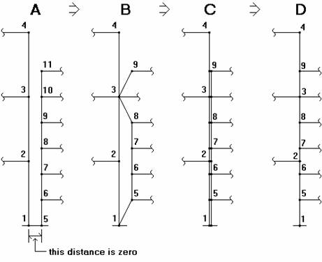
Diagram A shows the model before a merge. The two column lines
are separated in diagrams A and B strictly for ease of viewing, they should
be considered to be right on top of each other.
Step 1 of the merge eliminates duplicate joints changing the model from
diagram A to diagram B. On diagram A,
Step 2 looks for crossing members, however, there aren't any for this
particular example. Members that are parallel to each other aren't
treated as "crossing"
since the end
Step 3 is where the members are scanned for intermediate span
Step 4 eliminates duplicate members, in this case those that were created in step 2. This takes us from diagram C to diagram D. Looking at diagram C, the duplicate members are shown as the double lines. The first member listed on the Member spreadsheet is maintained and the other member is deleted. Any loads applied to the deleted member are transferred to the remaining member.
The final merged model is shown in diagram D. The column line is now comprised of 8 members, 1-5, 5-6, 6-2, etc. up to member 9-4.
Perform a Model Merge
To perform a Model Merge:
-
In the current model view window, select the items you wish to merge.
Typically you will want everything to be selected.
- Go to the Modify ribbon.
- Click on the Model Merge icon to bring up the model merge parameter window.
-
Set the parameters for the new merge.
For help on an item, click the
 Help icon and then click the item.
 - Click Apply All or Apply Selected to apply the model merge to the entire model or items you selected.
